
NERM Series 20-100 KVA Three-Phase Modular / Redundant True Online UPS Systems
- Formally Qualified to MIL-STD-1399, MIL-STD-461, MIL-STD-167-1A, MIL-S-901D Grade A, MIL-STD-810, MIL-STD-740-2, MIL-STD-2036, and MIL-STD-1474E
- For COTS and Modified COTS Systems
- High Input Power Factor (>0.99) With Low Input THD-i (<3%)
- Adaptability For Linear and Non Linear Load
- Low Audible Noise System Design (<55db)
- Double DSP Controller For Each Individual Power Module
- Digital Control For All Major UPS Subassemblies Including Rectifier, Inverter, Battery Charger, and Battery Discharge
- IGBT Modules Rather Than Discrete Semiconductor Components Are Used In the Power Module For High Reliability
- Conformal Coated Boards For Humidity Resistance
- Available PDU With Circuit Breakers and MS Connectors
- Built In Circuit Breakers For Cabinet AC Input, AC Output and Maintenance Bypass
- Digital Paralleling Technology With Very Low Circulating Current Between Power Modules
- Front Access Cabinet With Both Top and Bottom Cable Connections
- Each Individual Module Is Configured With An Independent DSP Controller To Avoid Single Point Of Failure Risk
- Generator-Friendly Interface
- RS232, 485, and Dry Contacts All Standard
- SNMP Available
- Description
- Models
- Specifications
- Popular Options
- System Compliance
- Videos
- Data Sheets
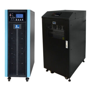
Description
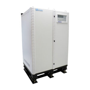
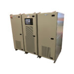
Nova Electric’s Rugged NERM-Series True Online UPS provides a modular backup solution for military data centers, computer systems, and any other critical equipment which requires dependable backup power in harsh environment applications. These units are specifically designed for demanding applications in high shock, vibration, humidity, and EMI environments in compliance to MIL-STD-1399, MIL-STD-461, MIL-STD-167-1A, MIL-S-901D Grade A, MIL-STD-810, MIL-STD-740-2, MIL-STD-2036, and MIL-STD-1474E.
The NERM’s state of the art design combines the latest IGBT three-level technology along with modern DSP Control for maximum reliability, low THD-i, and extremely high system efficiency. Modules can be stacked from 20 KVA to 100 KVA, offering hot-swappable flexibility with the highest quality. Power expansion is very simple to achieve by adding more individual power modules to the system, which can reach 100 KVA power. Two racks can be paralleled to reach 200 KVA power. These units are the ideal choice for:
- Shipboard
- Radar Systems
- Shelter Mounted
- Carrier Based Systems
- High Shock Applications (With Shock Mounts)
- Mobile Data Centers
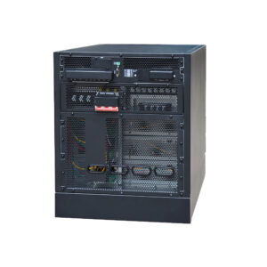
MODULAR HOT SWAP N+X DESIGN
Each UPS power module is designed to be hot swappable for hassle-free power expansion and system maintenance. Each module is controlled independently, thus avoiding a single point failure risk. If any individual module fails or disconnects, the system continues to operate and supply power without interruption, ensuring a high level of reliability and protection.
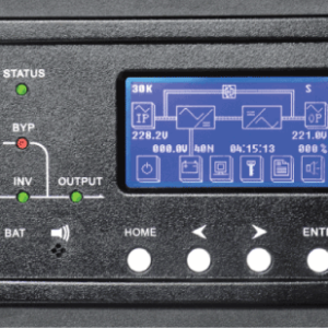
EASY OPERATION AND INSTALLATION
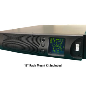
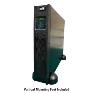
The modular flexibility of the NERM-Series UPS dramatically reduces technician time spent on installation and maintenance. A large touchscreen LCD panel ensures that users can quickly and easily access vital information.
INTELLIGENT BATTERY MANAGEMENT
Each UPS module contains a powerful 3.2 KW battery charger, and up to 4 modules can be paralleled for 12.8 KW maximum battery charging capacity. These chargers are DSP
controlled with intelligent digital algorithms designed specifically to prolong battery life.
SMART PROTECTION SYSTEM
Each individual power module and the overall system are protected by both hardware and software. Protection functions include abnormal current, incorrect input or output voltage, over temperature, and short circuit. The combination of these hardware and software protection functions results in extremely high reliability, with a very user friendly interface.
HIGH RELIABILITY DESIGN
The low-loss integrated three-level IGBTs used in each NERM-Series power module result in higher efficiency and enhanced reliability due to lower heatsink temperatures.
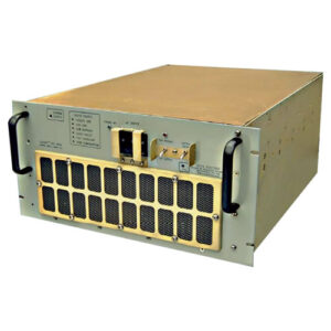
ROBUST CABINETS
All cabinets within this system are rugged and when shock mounted will pass the barge test specified in MIL-S-901D Grade A, as well as the MIL-STD-810 and MIL-STD-167A parameters as shown under the SYSTEM COMPLIANCE tab.
EMI / INPUT RF
These units contain input Power Factor Control which allows very low input THD-i, along with high PF at the input. NERM UPS can meet MIL-STD-461 EMI requirements optionally, along with MIL-STD-1399 for input THD-i, phase balance, and other relevant characteristics.
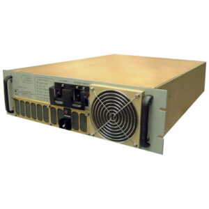
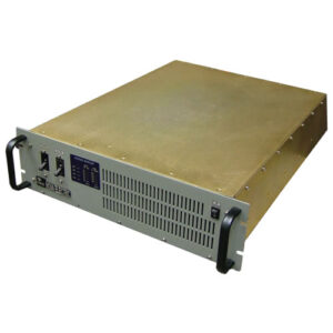
MODULE FEATURES
Hot swap building block 20 KVA modules @ 120/208 VAC
• Independent control
• Designed for parallel operation with active current sharing
• Designed for (N+1) redundancy
• Capable of hot swap
• Automatic mechanical disconnection in case of failure or maintenance
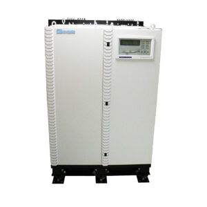
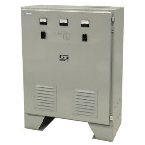
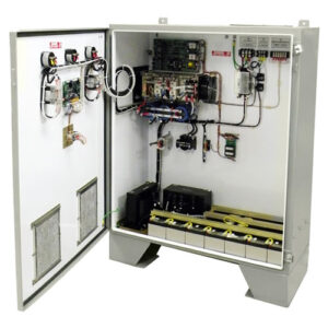
TRANSFORMER ISOLATION AND MANUAL BYPASS
An optional cabinet which provides for input and output isolation is required for any voltage without a neutral. This cabinet may also be used for applications with a neutral where complete Input / Output isolation is desired. This cabinet can also contain a mechanical rotary manual bypass switch used to isolate the UPS electronics enclosure for safe service while maintaining power to the load. When manual bypass is used, customer AC Input / Output will be made to this cabinet. This cabinet will also contain an input circuit breaker and EMI filtering when MIL-STD-461 requirements are specified. An output PDU may be included in this enclosure. We can provide an array of output distribution with various customer specified MS connectors.
BATTERY CABINET
The system batteries may be housed in a separate (matching) enclosure with a protective circuit breaker, or separate racks depending on run time desired. When the batteries are housed inside the matching enclosure, multiple strings will be used in parallel for highest redundancy. The batteries may be drawer mounted or on rails within the enclosure.
| MODEL | KVA | KW | INPUT / OUTPUT (VAC) | UPS CABINET DIMENSIONS (WxDxH) | BATTERY CABINET DIMENSIONS (HxWxD) | RUN TIME AT FULL LOAD | TRANSFORMER CABINET DIMENSIONS | |
|---|---|---|---|---|---|---|---|---|
| NERM11-20K3/6-120/208-120/208 | 20 | 18 | 120/208 Input / Output | 23.6 x 35.5 x 63” | Internal to UPS Cabinet | 40x 9 AH cells for 2 minutes at 18 kW load or 80x 9 AH cells for 10 minutes at 18 kW load | Available for applications requiring isolation and for EMI and PDU requirements | QUOTE |
| NERM11-40K3/6-120/208-120/208 | 40 | 36 | 120/208 Input / Output | 23.6 x 35.5 x 63” | 23.6 x 35.5 x 63” | 40x 26 AH cells for 5 minutes at 36 KW load | Available for applications requiring isolation and for EMI and PDU requirements | QUOTE |
| NERM11-60K3/6-120/208-120/208 | 60 | 54 | 120/208 Input / Output | 23.6 x 35.5 x 63” | 23.6 x 35.5 x 63” | 60x 26 AH cells for 5 minutes at 54 KW load | Available for applications requiring isolation and for EMI and PDU requirements | QUOTE |
| NERM11-80K3/6-120/208-120/208 | 80 | 72 | 120/208 Input / Output | 23.6 x 35.5 x 63” | Two Cabinets Needed - Each Cabinet is 23.6 x 35.5 x 63” | 80x 26 AH cells for 5 minutes at 72 KW load | Available for applications requiring isolation and for EMI and PDU requirements | QUOTE |
| NERM11-100K3/6-120/208-120/208 | 100 | 90 | 120/208 Input / Output | 23.6 x 35.5 x 63” | Two Cabinets Needed - Each Cabinet is 23.6 x 35.5 x 63” | 100x 26 AH cells for 5 minutes at 90 KW load | Available for applications requiring isolation and for EMI and PDU requirements | QUOTE |
| NERM11-20K3/6-450(D)-120/208 | 20 | 18 | 450 Delta Input / 120/208 Wye Output | 23.6 x 35.5 x 63” | Internal to UPS Cabinet | 40x 9 AH cells for 2 minutes at 18 kW load or 80x 9 AH cells for 10 minutes at 18 kW load | 23.6 x 35.5 x 63” | QUOTE |
| NERM11-40K3/6-450(D)-120/208 | 40 | 36 | 450 Delta Input / 120/208 Wye Output | 23.6 x 35.5 x 63” | 23.6 x 35.5 x 63” | 40x 26 AH cells for 5 minutes at 36 KW load | 23.6 x 35.5 x 63” | QUOTE |
| NERM11-60K3/6-450(D)-120/208 | 60 | 54 | 450 Delta Input / 120/208 Wye Output | 23.6 x 35.5 x 63” | 23.6 x 35.5 x 63” | 60x 26 AH cells for 5 minutes at 54 KW load | 23.6 x 35.5 x 63” | QUOTE |
| NERM11-80K3/6-450(D)-120/208 | 80 | 72 | 450 Delta Input / 120/208 Wye Output | 23.6 x 35.5 x 63” | Two Cabinets Needed - Each Cabinet is 23.6 x 35.5 x 63” | 80x 26 AH cells for 5 minutes at 72 KW load | 23.6 x 35.5 x 63” | QUOTE |
| NERM11-100K3/6-450(D)-120/208 | 100 | 90 | 450 Delta Input / 120/208 Wye Output | 23.6 x 35.5 x 63” | Two Cabinets Needed - Each Cabinet is 23.6 x 35.5 x 63” | 100x 26 AH cells for 5 minutes at 90 KW load | 23.6 x 35.5 x 63” | QUOTE |
All models shown available with N+X where X = the number of modules in redundancy. 100 kVA models can only have N+1. Shorter and longer battery run times on most models are available upon request.
| CABINET | SIZE* ( W X D X H) | WEIGHT – ESTIMATE (LBS) |
|---|---|---|
| UPS CABINET (CAN FIT UP TO 6 MODULES) | 23.6” x 35.5” x 63″ | 600 lbs (4 Modules) |
| BATTERY CABINET | 23.6” x 35.5” x 63″ | 800 – 1500 lbs (Depends on Battery Selected) |
| TRANSFORMER, MANUAL BYPASS, AND PDU CABINET | 23.6” x 35.5” x 63″ | 1500 lbs (60 KVA Model) |
| *Add ~8” to Height and Depth when Shock Mounts are Used (Mounts Add Significant Weight ) | ||
| CAPACITY | 20-100 KVA (18 – 90 KW) | |
| MAIN INPUT | ||
| INPUT VOLTAGE (W/NEUTRAL) | 120/208 VAC or 450 VAC DELTA (with Optional Transformer) – Other voltages available optionally | |
| INPUT FREQUENCY | 60 Hz (50 Hz Available) | |
| INPUT POWER FACTOR | > 0.99 at ½ Load to Full Load | |
| INPUT CURRENT THD (AT NOMINAL VOLTAGE) | < 3% at ½ to ¾ Load | |
| INPUT VOLTAGE WINDOW | -20% to +20% @ Full Load, -40% to +20% @ 70% Load or Less | |
| FREQUENCY WINDOW | 40-70 Hz Programmable | |
| BATTERY | ||
| BATTERY VOLTAGE | ± 120 VDC (Nominal) | |
| CHARGER POWER | 20% of UPS KW Power Rating | |
| CHARGER VOLTAGE PRECISION | 1% | |
| BYPASS | ||
| BYPASS VOLTAGE | Same as Input Voltage (see above) | |
| BYPASS VOLTAGE WINDOW | -20% ~ +15%, Full Load, Settable | |
| BYPASS OVERLOAD CAPACITY (PLEASE ADVISE US OF ANY INTENDED MOTORS IN THE LOAD) |
< 125%, Long Term Operation (2 Hours Maximum) | |
| 125% < load < 130%, for More than 1 Hour | ||
| 130% < load < 150%, for More than 6 Minutes | ||
| > 1000%, for More than 100ms | ||
| OUTPUT | ||
| OUTPUT VOLTAGE | 120/208 VAC or 450 VAC DELTA (with Optional Transformer) – Other voltages available optionally | |
| VOLTAGE PRECISION | ± 1.5% (Balanced Load), ± 3% (Unbalanced Load) | |
| VOLTAGE THD | THD < 2% (Linear Load), THD <5% (Nonlinear Load) | |
| POWER FACTOR | 0.8 Lead to Lag | |
| PHASE TOLERANCE | 120° ± 0.5° (Balanced and Unbalanced Load) | |
| CREST FACTOR | 3:1 | |
| OVERLOAD CAPABILITY | Up to 105%, Continuous Operation Up to 110%, Transfer to Bypass after 1 Hour Up to 125%, Transfer to Bypass after 10 Minutes Up to 150%, Transfer to Bypass after 1 Minute > 150%, Transfer to Bypass after 200 ms |
|
| SYSTEM | ||
| SYSTEM EFFICIENCY | Normal Mode: 90% (~89% with Transformers) | |
| ECO Mode: 99% | ||
| BATTERY MODE EFFICIENCY | 90% | |
| DISPLAY | LCD+LED, Touch Screen and Keyboard | |
| IP CLASS | IP20 Standard – Higher IP Ratings / Drip Shield Available Optionally | |
| INTERFACE (COMMUNICATION PORTS) | RS232, RS485, Dry Contacts, SNMP Card, EPO, Generator Interface | |
| INSTALLATION/CONNECTION | Top or Bottom Cable Connection (Custom Available) | |
| OPERATION TEMPERATURE | 0-40°C (to 50°C with 15% Derating) | |
| STORAGE TEMPERATURE (ELECTRONICS) | -25°C TO +70°C (Depends on Battery Rating) | |
| RELATIVE HUMIDITY | 0-95% (Non-Condensing) | |
| NOISE (dBa) | < 55 dBa at 5 Feet | |
MANY COTS OPTIONS AVAILABLE
- VRLA Batteries in Modular Drawers
- VRLA Batteries in a Separate Matching Cabinet or in an Open Rack
- Premium Wide Temperature Batteries
- Battery Circuit Breaker
- SNMP communications Card (with options for one way and bi-directional communications with enhanced security protocols such as V3.0 and SHA-384 (384-bit) encryption)
- Battery Temperature Compensation Module
- User Replaceable Air Filter for Dusty Environments
- Parallel Operation Kit
- Input Isolation Transformer
- Alternate Remote Shutdown / EPO Configurations
- Battery Cold Start Module (Allows the UPS to Start on Battery Alone)
- Input Surge Suppression Module
- Custom / Standard Shock Isolation Mounts – mount selection will vary depending on the number of UPS modules used, the input transformer kVA rating (if used,) the battery type, and number of batteries because the shock mount selection is weight sensitive.
- Special Paint Colors and Processes
- Special Welding Processes
- Modified ATP and FAT documents per customer requirements.
- Qual testing similar to tests shown under the compliance tab, or other tests as may be needed.
- Program Support for Industry Std SDRLs
- Custom Instruction and Maintenance Manuals
- On-Site Factory Support
Select models in the NERM product family were formally tested and qualified as follows:
MIL-STD-1399 Section 300B: For Type I Apparatus
- Voltage and Frequency Tolerance Test
- Voltage and Frequency Transient Tolerance and Recovery Test
- Voltage Spike Test
- Emergency Condition Test
- Grounding Test
- User Equipment Power Profile Test
- Current Waveform Test
- Voltage and Frequency Modulation Test
- Simulated Human Body Leakage Current Tests for Personnel Safety
MIL-STD-740-2: Structureborne Vibratory Acceleration Measurements for Type III Equipment
Additional Ruggedization to meet MIL-S-901D Grade A, MIL-STD-167, MIL-STD-810, and MIL-STD-2036: The UPS System’s construction is extremely robust, and ruggedized throughout. All components and modules within the unit are mounted using additional steel brackets and heavy-duty stainless-steel hardware, which is then further secured using Loctite and RTV where required. All boards are conformal-coated (Acrylic MIL-I-46058 Type R) for maximum resistance to potential condensation and fungus growth.
MIL-S-901D Grade A
MIL-STD-167-1A:
- Exploratory Vibration Test
- Variable Frequency Vibration Test
- Endurance Vibration Test
MIL-STD-810H:
- Operational Atmospheric Pressure Extremes per MIL-STD-810H, Method 500.6, Procedure II
- Air Temperature – Internal Mounted Equipment per MIL-STD-810H, Method 502.7, Procedure II (Low Temperature) and 501.7 Procedure II (High Temperature)
- Operational Vibration Test per MIL-STD-810H, Method 514.6
- Temperature – Transportation and Storage Extremes per MIL-STD-810H Methods 501.7 and 502.7 Procedure I
- Atmospheric Pressure Extremes per MIL-STD-810H, Method 500.6, Procedure I
- Rapid Decompression per MIL-STD-810H, Method 500.6, Procedure III
- Operational Humidity per MIL-STD-810H, Method 507
MIL-STD-2036: Operational Humidity
MIL-STD-1474E: Airborne Noise Production
MIL-STD-461G:
- CE101 Conducted Emissions 30 Hz to 10 kHz AC Power Leads from Ship Power
- CE102 Conducted Emissions 10 kHz to 10 MHz AC Power Leads
- CS106 Conducted Susceptibility Transients Modified AC Power Leads from Ship Power (Tested as part of CS116 per MIL-STD-461G)
- CS114 Conducted Susceptibility Bulk Cable Injection 10 kHz to 200 MHz
- CS116 Conducted Susceptibility, Damped Sinusoidal Transients, 10 kHz to 100 MHz
- RE101- Radiated Emissions, Magnetic Field. 42 (compliant at relaxed distances of 40 cm above the UPS)
- RE102 – Radiated Emissions, Electric Field, 10 kHz to 18 GHz 55 Antenna Positions
- RS101 – Radiated Susceptibility, Magnetic Field
- RS103 Radiated Susceptibility, Electric Field, 2 MHz to 18 GHz
Please note: Not all models and choices of input voltages and output voltages shown in the model chart have been formally tested for each of the following MIL-STD-461G parameters shown above. In such cases, Nova cannot guarantee full compliance without a formal testing program for your specific UPS configuration, available optionally. Please consult the factory for details.
Formal Qual Testing to these and other standards is available optionally.