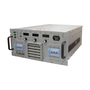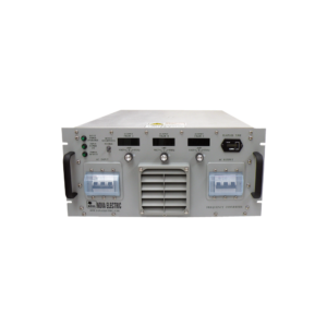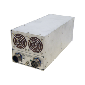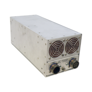

NGFCPFCRK Series 375 VA – 10.5 KVA Rack Mount Solid-State Three Phase Frequency Converters
- Solid-State Design
- Pure Sine Wave Output
- Extremely Rugged Construction Suitable For Harsh Environments
- High Reliability – MTBF Exceeds 100,000 hours
- Overload, Overvoltage, and Overtemp Protected
- MTTR below 30 minutes
- Lightweight, Compact Form Factor
- Tight Voltage and Frequency Regulation
- Custom Voltages and Frequencies Available
- Conformal Coated PCBs and All Stainless Steel Hardware
- Description
- Models
- Specifications
- Popular Options
- System Compliance
- Data Sheets
Description
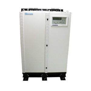
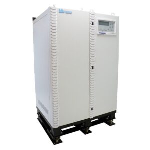
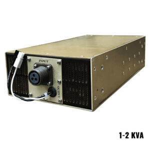
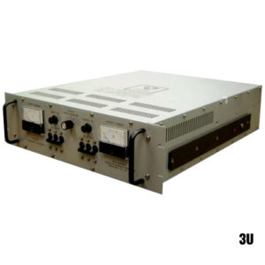
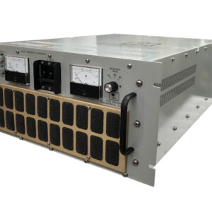
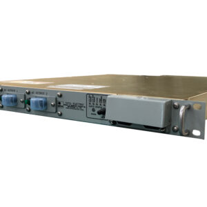
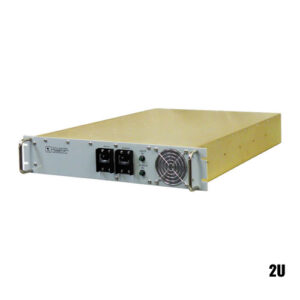
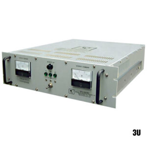
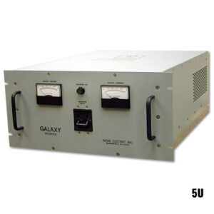
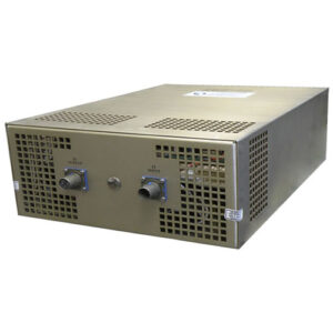
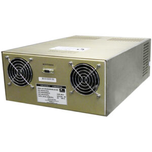
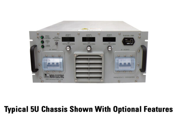
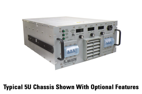
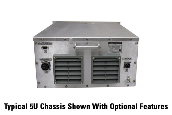
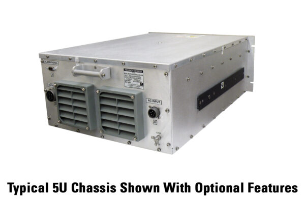
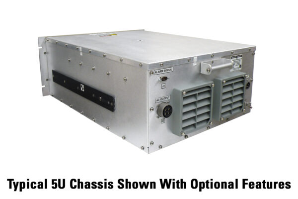
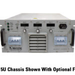
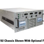
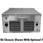
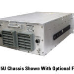
Nova’s NGFCPFCRK-Series frequency converters are high-reliability three-phase power sources specifically designed for demanding applications in high shock, vibration, humidity, and EMI environments. They can be built to meet MIL-STD-1399, MIL-STD-810, MIL-STD-167, MIL-S-901, MIL-STD-461, and other standards optionally. The NGFCPFCRK Series utilizes an advanced high frequency topology for light weight, compact form factor from 1-5U. These models are especially suitable for severe environment and high reliability applications such as:
- Military Applications: HMMWV, UAV, Shipboard, Submarine, Aircraft and Mobile Power Units, Shelters
- Aircraft Power
- Communications Systems
- Cellular Sites
- European Power / Export Testing
- Power Conditioning & Frequency Stabilization
- U.S. Power Abroad
- Railroad Signaling Power
| PARTIAL MODEL NO. | KVA | KW | OUTPUT VOLTAGE (VAC) | OUTPUT FREQUENCY (HZ) | WEIGHT (LBS.) | SIZE IN. (H x W x L) | |
|---|---|---|---|---|---|---|---|
| NGFCPFCRK0.3K3/5 | 0.375 | 0.3 | 220/380 | 50 | 26 | 1.75 x 19 x 24 | QUOTE |
| NGFCPFCRK0.3K3/6 | 0.375 | 0.3 | 120/208 | 60 | 26 | 1.75 x 19 x 24 | QUOTE |
| NGFCPFCRK0.3K3/4 | 0.375 | 0.3 | 115/200 | 400 | 26 | 1.75 x 19 x 24 | QUOTE |
| NGFCPFCRK3K3/5 | 3 | 2.4 | 220/380 | 50 | 35 | 3.5 x 19 x 24 | QUOTE |
| NGFCPFCRK3K3/6 | 3 | 2.4 | 120/208 | 60 | 35 | 3.5 x 19 x 24 | QUOTE |
| NGFCPFCRK3K3/4 | 3 | 2.4 | 115/200 | 400 | 35 | 3.5 x 19 x 24 | QUOTE |
| NGFCPFCRK4.5K3/5 | 4.5 | 3.6 | 220/380 | 50 | 46 | 8.75 x 19 x 24 | QUOTE |
| NGFCPFCRK4.5K3/6 | 4.5 | 3.6 | 120/208 | 60 | 46 | 8.75 x 19 x 24 | QUOTE |
| NGFCPFCRK4.5K3/4 | 4.5 | 3.6 | 115/200 | 400 | 46 | 8.75 x 19 x 24 | QUOTE |
| NGFCPFCRK6K3/5 | 6 | 4.8 | 220/380 | 50 | 60 | 8.75 x 19 x 24 | QUOTE |
| NGFCPFCRK6K3/6 | 6 | 4.8 | 120/208 | 60 | 60 | 8.75 x 19 x 24 | QUOTE |
| NGFCPFCRK6K3/4 | 6 | 4.8 | 115/200 | 400 | 60 | 8.75 x 19 x 24 | QUOTE |
| NGFCPFCRK10.5K3/5 | 10.5 | 8.4 | 220/380 | 50 | 65 | 8.75 x 19 x 24 | QUOTE |
| NGFCPFCRK10.5K3/6 | 10.5 | 8.4 | 120/208 | 60 | 65 | 8.75 x 19 x 24 | QUOTE |
| NGFCPFCRK10.5K3/4 | 10.5 | 8.4 | 115/200 | 400 | 65 | 8.75 x 19 x 24 | QUOTE |
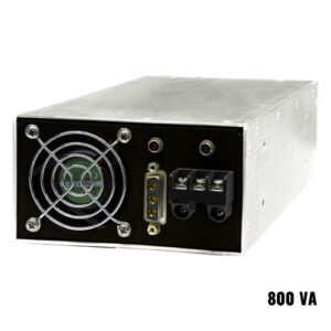
- Power Ratings: 375 W – 10.5 KVA
- Input Voltage: Most standard AC voltages including 115, 120, 200, 208, 220, 240, 277, 380, and 480 VAC single phase or 120/208, 115/200, 220/380, and 277/480 VAC three phase DELTA or WYE.
- Output Voltage: Most standard three phase AC voltages including 120/208, 115/200, 220/380, and 277/480
- Input Frequency: 50 Hz, 60 Hz, or 400 Hz – Custom Frequencies Available Optionally
- Output Frequency: 50 Hz, 60 Hz, or 400 Hz (+/-0.5%) – Custom Frequencies Available Optionally
- Frequency Regulation: +/-0.5% N.L. to F.L.
- Frequency Transients: None
- Voltage Regulation: +/-1.5% N.L. to F.L.
- Efficiency: Approximately 80-88% (depending on model)
- Output Total Harmonic Distortion: <3% Typical
- Overload: 125% for 5 minutes
- Typical Power Factor: 0.7 Lead to 0.7 Lag
- Input Circuit Protection: Circuit Breaker / Fuses, Transient Suppressors
- Circuit Protection: Current Limit, Short Circuit Protection, Thermal Protection, and Semi-Conductor Protection
ENVIRONMENTAL & MECHANICAL
- Operating Temp: -20°C to +50°C Standard – Extended Range available optionally
- Storage Temp: -40°C to +71°C
- Cooling: Forced Air by internal fans
- Vibration: Normal shipping and handling – Designed to meet MIL-STD-167 optionally
- Shock: 20g, 11 mS half sinewave – Designed to meet MIL-STD-810 optionally
- Elevation: 10,000 ft. typical
- Humidity: to 95% RH non-condensing – Designed to meet MIL-STD-810. All boards conformal coated with Acrylic MIL-I-46058 Type R.
- EMI: Designed to meet MIL-STD-461 with optional additional filtering.
- MTBF: 30,000+ hours typical per MIL-HDBK-217
- MTTR: Less than 30 minutes.
OPTIONS
- Ruggedization against high shock, vibration and humidity
- MS connector mates
- Multiple output outlets
- Chassis Slide Guides
- Rugged Transit Cases and Custom Enclosures
- 400 Hz input and / or output
- CAD Free Connectors
- Non-PVC wiring
- High IP Protection for front / rear panels (typically IP32) including louvers on all intake and exhaust, as well as fully gasketed breakers, switches, and indicators.
- AUX DC Outputs
- Digital Input and / or Output Volt and Amp Meter Set (available on select models)
- Elapsed Time Meter (available on select models)
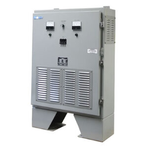
- Power Distribution Units (PDUs)
- Environmental Stress Screening Services
Select models outfitted with the appropriate ruggedization and filtering options in this product family were formally tested and qualified as follows:
MIL-STD-1399, Section 300B Input Power Test:
5.3.1 Voltage and Frequency Tolerance Test
5.3.2 Transient Voltage and Frequency Tolerance and Recovery Test
5.3.3 Voltage Spike Test
5.3.4 Emergency Condition Test
5.3.5 Grounding Test
5.3.6 User Equipment Power Profile Test w/Exceptions
5.3.7 Current Waveform Test
5.3.8 Voltage and Frequency Modulation Test
5.3.9 Simulated Human Body Leakage Current Test for Personnel Safety w/Exceptions
5.3.10 Equipment Insulation Resistance Test
5.3.10 Active Ground Detector Test
MIL-STD-167-1A Vibration Test: The Frequency Converter was subjected to Type I vibration through the frequency range of 4 Hz to 33 Hz in each of the three (3) major axis in accordance with MIL-STD-167-1A.
MIL-S-901D Shock Test: The Frequency Converter was subjected to three (3) positive and three (3) negative 20 g, 11 msec, ½ Sine Wave shock pulses in each of the three (3) axes in accordance with the referenced MIL-S-901D specifications (Grade A) for a total of eighteen (18) shock pulses.
MIL-STD-461E EMI Test (Navy, Submarine Application):
CE101, Conducted Emissions, Power Leads, 120 Hz to 10 kHz
Limit: Figure CE101-2, Limit for Surface Ships and Submarine Applications, 60 Hz
CE102, Conducted Emissions, Power Leads, 10 kHz to 10 MHz
Figure CE102-1, CE102 Limit for All Applications, Basic Curve + 12 dB w/Exceptions.
CS101, Conducted Susceptibility, Power Leads, 120 Hz to 150 kHz
Figure CS101-1, CS101 Voltage Limit for All Applications, Curve # 1
CS106, Conducted Susceptibility, Transients, Power Leads
Limit: Figure CS106-1, CS106 Voltage Limit
CS114, Conducted Susceptibility, Bulk Cable Injection, 10 kHz to 200 MHz
Limit: Figure CS114-1, CS114 Calibration Limits
4 kHz to 1 MHz, 77 dBuA
10 kHz to 30 MHz, Curve # 1
30 MHZ to 200 MHz, Curve # 2
RE101, Radiated Emissions, Magnetic Field, 30 Hz to 100 kHz
Limit: Figure RE101-2, RE101 Limit for Navy Applications w/Exceptions.
RE102, Radiated Emissions, Electric Field, 10 kHz to 18 GHz
Limit: Figure RE102-2, RE102 Limit for Submarine Applications, Internal to Pressure Hull
RS103, Radiated Susceptibility, Electric Field, 2 MHz to 18 GHz
Field Strength:
2 to 30 MHz: 5 V/m
30 MHz to 18 GHz: 10 V/m
Modulation: 1 kHz pulse, 50% duty cycle
Environmental – Designed to Meet*:
MIL-STD-810G, Method 501.5, Procedure II. TH=+45C high temperature (operating) testing
MIL-STD-810G, Method 502.5, Procedure II. TL=+5C low temperature (operating) testing
MIL-STD-810G, Method 507, Procedure II. <95% Non-Condensed Relative Humidity (operating / non-operating)
Ambient Operating Pressure between 750 and 1200 millibars.
Ingress Protection per IP54.
Operating Attitude for both Front to Back and Side to Side of +/- 30 degrees.
Audible Noise of 60dBA Maximum.
*Compliance to these “designed to meet” environmental standards based on similarity to previously qualified designs. Formal Qual Testing to these and other standards is available optionally.